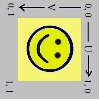
First of all I would like to introduce "smile". "Smile" will follow us through this tutorial as the bitmap we will use when applying textures.
So how do we do this simple applying of smile on a 4-sided polygon as shown in the rwx file below? To answer that I will walk you through it, at this point (and in other examples) it is recommended that you use a piece of paper and draw the object. The object consist of 4 vertices (4 points in space). By applying a Quad command we form a polygon with 4 sides (a Quad by definition has 4 sides).
All polygons is one-sided, meaning it is visible only from one side. The rule to from which side this polygon is visible is that its visible when the vertices is numbered in counter clockwise order (from your point of view). The hash mark is used here to show the numbering of the vertices, they do not in any way govern the numbering. If you are unsure at this point draw the points on paper. The first number is the x location (left and right on paper), the second number is is the height above ground (up and down on paper) and the third number is the depth
ModelBegin
surface .5 .3 0

ClumpBegin
   Vertex -.2  0 0 #1
   Vertex  .2  0 0 #2
   Vertex  .2 .4 0 #3
   Vertex -.2 .4 0 #4

   color 1 1 0

   Quad 1 2 3 4

   ClumpEnd

ModelEnd
The model looks like this with (with yellow colour):
Just as we use x, y and z values to describe our where our points in space is to be (vertices) we use numbers to describe the texture status at each vertex involved in each polygon.
A texture is flat, on other words 2-dimensional, so we need only 2 additional numbers at each vertex when using textures.
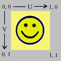
To not to confuse our 2-dimensional texture information with our 3-dimensional object information they are not called x,y or z but u and v. U is the horizontal distance across the texture and V is the vertical distance across the texture.
The more I think about this this scheme it seems wiser and wiser to me because texture information and physical space information is two different pieces of information. They are connected but not the same.
Lets get down to the practical level. We need to put in more information in our rwx file. We will stretch the bitmap "smile" over our single-surface object. Now a things that is not negotiable is which corner the is the starting point. In rwx files the graphics starts in the upper left corner. If you are used to school mathematics you are used to origo being in the lower left corner. In rwx files the origo (or u=0 and v=0) is in the upper left corner. Nerds was here first!
Imagine our square 4-sided polygon (Quad in rwx) and lets put in the texture information (uv part).
We will look at this vertex by vertex in the modified rwx file:
ModelBegin
surface .5 .3 0

ClumpBegin
   Vertex -.2  0 0 uv 0 1 #1
   Vertex  .2  0 0 uv 1 1 #2
   Vertex  .2 .4 0 uv 1 0 #3
   Vertex -.2 .4 0 uv 0 0 #4

color 1 1 0

Texturemodes lit foreshorten

Texture smile

Quad 1 2 3 4

ClumpEnd

ModelEnd
We begin with vertex #4 which is the upper left corner, it has the UV values 0 0 which means that we have moved along the texture at zero horizontal and vertical distance and nailed that point of the texture to that vertex. In other words: the upper left corner of the texture is at the upper left corner of the polygon.
If we move over to the upper right corner (vertex #3) you see it has UV 1 0. That means the we are at the far right side of the texture (that's the number "1") and still at the top edge (the number "0").
Vertex #1 follow the same pattern but here we have moved all the way down to the bottom edge of the texture.
Last is Vertex #2 which has UV 1 1, meaning that the lower right corner of the texture is pinned on this vertex.
To sum up this example: A texture has its own coordinate system called U V and the values vary between 0 and 1, the origo is at the upper left corner (UV 0 0) and the opposite corner has UV 1 1.
Negative numbers is not allowed as UV values.
This can be illustrated like this:
So what happens if we go past 1? Simple: the texture will start over again. I like to think of this as like laying tiles on a wall. Lets do this on our example file:
ModelBegin
surface .5 .3 0

ClumpBegin
   Vertex -.2  0 0 uv 0 1 #1
   Vertex  .2  0 0 uv 2 1 #2
   Vertex  .2 .4 0 uv 2 0 #3
   Vertex -.2 .4 0 uv 0 0 #4

   color 1 1 0

   Texturemodes lit foreshorten

   Texture smile

   Quad 1 2 3 4

ClumpEnd

ModelEnd
As you see we have now doubled the horizontal value and that is a way of telling that "over this distance I want this texture to be mapped twice". This will look like this:
The image is now horizontally compressed as the polygon itself is unchanged.
For fun we can do the same vertically, but we will tile 3 times this time.
ModelBegin
surface .5 .3 0

ClumpBegin
   Vertex -.2  0 0 uv 0 3 #1
   Vertex  .2  0 0 uv 2 3 #2
   Vertex  .2 .4 0 uv 2 0 #3
   Vertex -.2 .4 0 uv 0 0 #4

   color 1 1 0

   Texturemodes lit foreshorten

   Texture smile

   Quad 1 2 3 4

ClumpEnd

ModelEnd
This will look like this:
The reason we may want to do this is to cover larger surfaces, if we didn't do this the texture will look unrealistic when looked at up.
In Active Worlds the rule of thumb is to use one tile for each 2 meter. A wall 8 meters wide and 4 meters high will have 4 tiles horizontally and 2 vertically. But remember that this is a rule you can break to achieve a desired effect.
You don't have to start a tile at the edge of it but can start at any point in it. In this example we will show 2 tiles and both are cut in half vertically.
How this is done is by introducing a offset in the UV values, in this example we have a horizontally offset of 0.5 and it looks like this:
ModelBegin
surface .5 .3 0

ClumpBegin
   Vertex -.2  0 0 uv  .5 1 #1
   Vertex  .2  0 0 uv 1.5 1 #2
   Vertex  .2 .4 0 uv 1.5 0 #3
   Vertex -.2 .4 0 uv  .5 0 #4

   color 1 1 0

   Texturemodes lit foreshorten

   Texture smile

   Quad 1 2 3 4

ClumpEnd

ModelEnd
The 0.5 offset cuts the texture precisely in the middle.
While we are at it lets do almost the same vertically but let it we will tile it one and a half time.
ModelBegin
surface .5 .3 0

ClumpBegin
   Vertex -.2  0 0 uv  .5 2  #1
   Vertex  .2  0 0 uv 1.5 2  #2
   Vertex  .2 .4 0 uv 1.5 .5 #3
   Vertex -.2 .4 0 uv  .5 .5 #4

   color 1 1 0

   Texturemodes foreshorten

   Texture smile

   Quad 1 2 3 4

ClumpEnd

ModelEnd
Here I will show how to apply only a small part of the texture on a polygon. We start at 0.3 both at both U and V and end at 0.7 at U and V.
ModelBegin
surface .5 .3 0

ClumpBegin
   Vertex -.2  0 0 uv .3 .7 #1
   Vertex  .2  0 0 uv .7 .7 #2
   Vertex  .2 .4 0 uv .7 .3 #3
   Vertex -.2 .4 0 uv .3 .3 #4

   color 1 1 0

   Texturemodes lit foreshorten

   Texture smile

   Quad 1 2 3 4

ClumpEnd

ModelEnd
This far we have applied the texture the way we do most of the time. Now lets rotate it 90 degrees to the right. We do that by placing the corners of the texture at different vertices (or in other words, we change the UV values at each vertex).
ModelBegin
surface .5 .3 0

ClumpBegin
   Vertex -.2  0 0 uv 1 1 #1
   Vertex  .2  0 0 uv 1 0 #2
   Vertex  .2 .4 0 uv 0 0 #3
   Vertex -.2 .4 0 uv 0 1 #4

color 1 1 0

Texturemodes lit foreshorten

Texture smile

Quad 1 2 3 4

ClumpEnd

ModelEnd
The change from example 1 is that we have moved the UV 0 0 location to the upper right vertex. One thing to notice here is that the horizontal axis (U) of the texture now actually points down vertically. The same for V which now points horizontally to the right. Its easier to write the mapping information (the UV values) and to visualise this if we take the drawing from example 1 and turn it 90 degrees to the right:
In the same way we apply a texture in any way we like, upside down, mirrored or even at an angle.
I will show that as a last point in this example without much explanation, this is for you to ponder upon :-)
ModelBegin
surface .5 .3 0

ClumpBegin
   Vertex -.2  0 0 uv .5  1 #1
   Vertex  .2  0 0 uv 1  .5 #2
   Vertex  .2 .4 0 uv .5  0 #3
   Vertex -.2 .4 0 uv 0  .5 #4

   color 1 1 0

   Texturemodes lit foreshorten

   Texture smile

   Quad 1 2 3 4

ClumpEnd

ModelEnd