A RenderWare script (RWX) file is an ASCII text file of an object/model's geometry. This geometry consists of vertices, polygons, and material information.
Writing a RWX file is like textual programming, although not nearly as complicated, but almost. Be prepared to spend a while learning all of RenderWare's terms and scripting commands.
| Formatting |
|---|
RWX formatting is how the ASCII text (or code) is laid out. You will probably get your own style of formatting if you make objects enough. Whatever works for you, go with it, but I believe the fewer blank lines, spaces, tabs, and extra zeroes RenderWare has to deal with, the faster it will process the RWX file. Andras' Reduce can remove most of them.
You can save typing by keeping everything lowercase, but if you're just starting out, mixed
case may be more helpful until you learn the script commands better.
These do not seem to make any difference to RenderWare, but I try not to use tabs, spaces, and blank lines too much, unless separating certain parts like vertices from material information from polygons.
Case
Blank Lines/Spaces/Tabs
RenderWare has many default commands, but most programs (and, hence, programmers) don't realize this and end up unnecessarily repeating them, causing an extra extraordinary amount of repetitive overredundant redundant redundancy--like the last part of this sentence. :) It just wastes space (bytes) and makes reading the RWX that more confusing.
If two or more prototypes have the same materials and texture(s), place them above (outside) the first "protobegin <name>" statement and the materials and/or texture(s) should be applied to and all prototypes afterwards will use them without having to specify them for each prototype. However, not all commands will work: textureaddressmode.
Some programs add UV coordinates in by default after saving. A quick way to remove them, (from Challagar; edited) is to "do a search and replace in [a text editor] 'UV' with '#UV', then open the model in RWXMod and save it again." RWXMod removes UV coordinates (and anything) with "#" before them.
I use # in this and other scripts to explain what is going on within an RWX file, as if the comments were in the script file itself.
This example script file will make a 1m x 1m x 0m panel/wall in Active World measurements
(remember .1m = 1m):
# Begin the clump:
clumpbegin
# Vertices can begin anywhere, but making the first one in the upper left corner makes it easier to map textures (see uv).
# Axis
# No material information is needed in this example since all the defaults are being used.
# Connecting vertices: polygons will only show on one side per polygon connection statement: ("quad", "triangle", or "polygon"); because the first vertex is in the upper left corner, the first "quad" statement will be listed clockwise, creating a 1-sided front polygon:
quad 1 2 3 4
# To get a back side, just reverse the vertex order (counterclockwise):
quad 4 3 2 1
# End the clump:
clumpend
This example is very primitive. For a more detailed look into basic RenderWare scripting, check out Grover's Renderware Tutorial.
Redundancy
UV Coordinates
Example Script
# X Y Z width height depth
vertex -.1 .1 0 # left 1m, up 1m, none
vertex .1 .1 0 # right 1m, up 1m, none
vertex .1 0 0 # right 1m, none, none
vertex -.1 0 0 # left 1m, none, none
| Collision Detection |
|---|
Collision detection is what happens when you bump/collide/run/walk into an object: you stop, move up the object or right through. An object's boundaries are shown by its bounding box (a yellow "highlighted" box around the object's edges and corners), but the bounding box isn't necessarily where collision detection will occur.
With the release of Active Worlds 2.2, AW increased its limit of 64 to 256 verts for full collision detection. In AW3 there is no longer a vert limit, so the next two paragraphs don't apply to it:
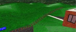
However, an object like the Corvette in the geometry/light sampling example is made up of 257+ vertices so if you, for instance, walked on the hood, up the front window, over the top, down the back window, and on the trunk, your altitude (height from 0m) would remain the same distance over all of it. Now, you may think "so what?", but have you ever tried to walk on some rocks and found you suddenly stopped for no apparent reason? Most likely it's because the rocks are more than 256 verts, or weren't positioned correctly [.5m is the maximum height objects with perpendicular (_|_) sides can be positioned in order to move up them]. For an example of this effect, first visit ![]() AlphaWorld 1172.4s 1242.9e,
AlphaWorld 1172.4s 1242.9e, ![]() Yellowstone, or
Yellowstone, or ![]() Mars. All of these worlds' rocks are all under 256 verts, so, if positioned correctly, can allow for a neat rock climb. Then visit
Mars. All of these worlds' rocks are all under 256 verts, so, if positioned correctly, can allow for a neat rock climb. Then visit ![]() AlphaWorld again and try walking on its bed01.rwx, which has over 245 verts and is completely solid instead of allowing climbing on the different-height bed posts and mattress.
AlphaWorld again and try walking on its bed01.rwx, which has over 245 verts and is completely solid instead of allowing climbing on the different-height bed posts and mattress.
Non-solidity
Non-solidity is something that isn't solid; you can walk through it without it stopping you; no collision detection is done. In Active Worlds, usually one types "create solid no" in the action field of an object's properties in order to make the object non-solid. This is fine for most cases, but it can be annoying when you may want an object to be non-solid automatically, or if an object is irregularly big (such as a tree with a shadowin which case the shadow, because it's flat and close to the ground (or even the same height depending on ground and if the tree is raised), causes the need for the tree (or at least the shadow) to be raised so as to not cause z-buffering. Usually one [Shift] movement up will fix this, but then if you walk on top of the solid shadow, you are .1m above the ground. So, one way of fixing this is to make the shadow non-solid which it should be anyway because in real life shadows have no solidity.
To make part of an object non-solid, for AW 2.2 and below, put a "clumpbegin" above it, and a "clumpend" below it (this is also known as heirachial/parent-child/nested clumping). In AW3+ the collision command must be used. Then in between go all the vertices, material information, polygons, etc, or if you have a prototype defined, just put the "protoinstance" command in the nested clump.
For an example of non-solidity using nested clumps and the collision command, see the tree shadow example.
From Roland (edited): "Avatar collision detection is checked against an oblong cube 1m wide (x-axis) by 1m deep (z-axis) and the same height as the avatar."
So <1m³ avatars are limited in x- and z-axis collision detection. Smaller avatars will "physically" collide before visually colliding, making it impossible for, for example, rat avatars to scurry in oil drums and garbage cans. Active Worlds should just use the avatar's bounding box instead.
Also, you may (or may not) notice that when traversing down sloped surfaces (like the "rolling" hills in Cubed), your avatar bounces up and down instead of smoothly, gradually, gliding down the slope. This is due to the world's gravity. It "steps" and recalculates the "settled" (non-moving) position once stopped ("step sinking"). While this effect might simulate "walking", it doesn't look right for non-walking avatars. Active Worlds now has adjustable gravity but avatar collision detection has changed (yet again) and is slower with other avatars and complex objects.
Note
| Complex Objects |
|---|
Perhaps one of the most daunting tasks facing beginning AW object makers is how to make objects that look real. Some turn to converting way too highly complex (lots of polys) objects made in 3D modellers without attempting to reduce their complexity, so their converted objects tend to grind AW to a halt and they're left wondering why. Such people fail to understand RWXes enough to simply make their own models or are not aware of the real-time-rendered nature of AW. I would recommend such people play any 3D games to better understand the meaning and effectiveness of low-poly objects.
From Grover (edited):
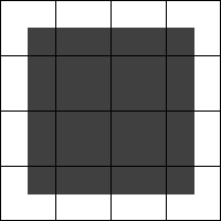
Discs
vertex 0 0 .1
And voila! 6 vertexes in a perfect mathematical circle. :)" Textured Discs
vertex 0 0 .1 uv 0 0
|
Spheres
scale .2 1 .2
Etc, etc, etc... I'm not going to create an entire piece hereyou can do that for yourselves. The x value of the uv needs changed for each row as well (anyone notice I accidentally did the uv example sideways? hehe) But, the process makes a lot of tough objects soo much easier to do!" |
Primitives
Primitives are a relatively quick and easy way of making complex objects. By using just a few primitives, rotate, translate, and prototype statements, I've found most seemingly complex and intricate objects are a snap to make. And, remember, RWXMod converts primitives to full vertex and polygon statements which can then be run through a texture mapper (but won't always UV correctly since all the RWX texture mappers I've ever tried can't do the more complex cubical, cylindrical, and spherical texture mapping). Then be sure to run it through a program like Andras' Reduce to remove all the extra crap RWXMod and texture mappers add to the RWX. From Starheart: AW 3.3+ will automatically texturemap primitives but texturemode lit must be enabled (which it is by default).
| Ground |
|---|
Infinite | Sectional
Infinite
Infinite (short for "infinitely repeating) ground objects repeat infinitely every 60m².
Most worlds usually have a flat ground object. This is the default type of Active Worlds ground and is fine for most worlds, but it can make worlds and building in them boring, monotonous, and even frustrating. The real world isn't flat (despite what the Flat Earth Society believes).
Non-Flat
Some worlds may have rolling hills, but it's still a single object and there's still a limit as to what's possible compared to the flexibility sectional ground types allow. ![]()
Sectional ground is made up of sections/parts/pieces/tiles (objects) built/made to fit together like a puzzle,
Modular | Benefits | Construction/Creation/Making | Issues/Problems | Examples
Modular
A subset (part) of, and similar to, sectional ground, modular ground is made up of modules built/made to fit together (like LEGO) and is more versatile building with than sectional ground.
Benefits
Construction/Creation/Making
Making sectional/modular ground by hand is a very daunting task. To create sectional/modular ground, keep the solidity limit in mind (be careful not to make the ground objects too big and complex so they become solid and not traversable, or non-solid and people fall through them). But even with the solidity limit, each ground object can still be fairly complex.
Lucio held a class in the AW University about his technique for creating modular ground. He used a program he made, LPMod to place the modules in a world. He also set up a Archon Manus (of Young Shamus' TerraFormer beta which had potential and may have been considered being integrated into AW (which would have made modelling ground much easier). AW 3.3 introduced terrain modelling but it's quite limited.
Issues/Problems
Because Active Worlds does not have better control over ground detection and gravity, some workarounds must be used or there will be problems using sectional/modular ground. If no ground is specified in the world options, gravity will not be enabled, and in order to go below 0m altitude (and above it) without being blocked by a seemingly invisible barrier, the infinitely repeating ground object must be non-solid (and you'll probably want to make it invisible as well). What I do to get around both of these problems is have the infinitely-repeating ground object as an empty clump:
clumpbegin That's it. This tricks Active Worlds into thinking there is a ground and fixes the other problems described above. The only drawback is that upon entering the world for the first time people will fall. To get around this, I install 30m x 0m x 30m bump teleport panels at -350m. However, because the building limit only goes to -327.67m altitude, yet you can move to -350m, it is possible people will fall to -350m before the teleport panels download and render. So by placing the panels at -350m (vertically translate them down 22.33m inside the RWX), they will always catch everyone (unless they move beyond the width of the bump panels of course).
Other people use different approaches to this: Rjinswand uses a 1m x 0 x 1m platform at exactly ground zero and a -50m altitude "net" as the infinitely-repeating ground object. The problem with this is that the platform prevents movement below it unless you walk off it. So at the next 60m² repeat, at 0m altitude will be another 1m x 0m x 1m platform, even though the actual ground surface might not even be anywhere near there so people may accidentally land on it and wonder what's going on and why they stopped. The other problem is the ground object can't be set to bump teleport/warp, so the "net" won't offer much of a solution to people falling. However, placing bump panels where the net is will alleviate this, but every 60m² the invisible net will block people from going any lower still.
I feel my way is the best until AW has better ground detection/gravity control, but feel free to experiment, and let me know if you come up with a better way.
I have found a semi-better way around the falling problem. Nest the empty clump in another empty clump:
clumpbegin But this only seems to make avatars hover 1m above 0m altitude until the ground object downloads. Then they fall like with the single empty clump in the first example. Ah well.
Examples
Examples of sectional/modular ground can be seen in the following worlds (some may be down and/or in other universes, and there are surely more worlds not listed here):
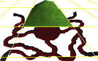
From Grover (edited): "I hinted towards it weeks ago, but now that Oct31 is open I can talk about the new system of mod grounds I developed for hell. :-) As you enter hell, you fall through the whirlpool and into a large chamber. Each of these is a single, completely solid object. As are the caves: the entire system of tunnels was built with 8 instances of two discreet objects. Thus, with a total of 10 objects, we created an entire ambiance, covered nearly 100m x 100m and incredibly it rendered twice as fast as expected(!) (allowing for many more animations). But the real trick lies with solidity. You'll notice two things about the mod ground I've been using: one is that they're 30m accross, much larger than anyone else has been using for modular ground. The other is that they're all incredibly complex: pre-built structures onto themselves with >64 vertexes. But still solid throughout without having to use "visible off" panels... Also, check out pretty much all of Dante's hell for more examples. The City of Dis is made completely out of macro mod grounds, as are the abysses of boiling blood and lava. The arches are singular objects built directly into the mod grounds. Same with the river Styx; they're all 30m side modular ground pieces, designed to make building a huge expanse quickly while keeping fine control of detail.
It's good for different things than the micro-scale mod grounds most people have been using. (And I have been *very* impressed with your work, guys!!) But at least another trick to add to our collective spell books. :-)
The yellow gridlines represent spacing of the mod ground pieces at 30m. The grass on top is an early 'hill' prototype i was playing with at the time... I superimposed the two in a photoeditor so the scale was wrong to try and draw the yellow lines on the lower part: it's 90m across, and the central chamber is 30m across. And yes, this is the current arrangement of hell, just in case you were wondering. ;-)"
Terrain
New for AW 3.3, terrain ground allows relatively easy ground manipulation, but only in 10x10 sections and without the ability to add action commands (no footstep sounds, for example) to the sections. It renders out to the far clipping plane limit (400m by default, depending on the world fog setting) which is nice to give the ground more continuity instead of abrubtly stopping at the visibility distance like before. It can also have "holes" created in it (simply blank cells) but in order to edit a holed cell it requires selecting a surrounding unholed cell and then moving the selection highlight over to the holed cell, which can be problematic if large areas are holed (and even impossible if the entire world is a hole, requiring a complete terrain reset or perhaps using a bot). Anyway, terrain offers some new possibilities with AW.
Sectional
![]() demo area in AWUniv world which may be of help.
demo area in AWUniv world which may be of help.
D'Magia world) has (had?) a terrain editor. Also see his journal for more info on it. See ![]() for these links.
for these links.
clumpend
clumpbegin
clumpend
clumpend
![]() ³ (Cubed)/Hole: 10/20m x n x 10/20m (and other size) modules I made in a text editor.
³ (Cubed)/Hole: 10/20m x n x 10/20m (and other size) modules I made in a text editor.
![]() Aardvark: Rjinswand's modular hills
Aardvark: Rjinswand's modular hills
![]() Ares: 20m x n x 20m sections made with AWCI's program, but still has an infinitely flat ground.
Ares: 20m x n x 20m sections made with AWCI's program, but still has an infinitely flat ground.
![]() D'Magia: Various-sized sections created by Archon Manus with his terrain generator, but still has an infintely flat ground.
D'Magia: Various-sized sections created by Archon Manus with his terrain generator, but still has an infintely flat ground.
![]() MidEarth: 30m x n x 30m sections made by Rjinswand.
MidEarth: 30m x n x 30m sections made by Rjinswand.
![]() Ravenstor: Modular ground-based "extreme visiblity" ground made by Rjinswand.
Ravenstor: Modular ground-based "extreme visiblity" ground made by Rjinswand.
![]() Rhapsody: Andras' modular ground experiment world made with his DEM-to-RWX converter!
Rhapsody: Andras' modular ground experiment world made with his DEM-to-RWX converter!
![]() Oct31: >30m x n x >30m sections made by Grover, but still has an infinitely flat ground.
Oct31: >30m x n x >30m sections made by Grover, but still has an infinitely flat ground.
 Techy note: Oh, and a word to the wise, if you're going to experiment with this, learn from my mistakes and don't put vertical walls on the extreme ends of 30m wide sections. collision detection breaks down on the very edge of cell borders, and people can sometimes run right through an otherwise solid wall... you can walk into it and you stop. but if you keep trying to walk into it, or hold down ctrl you'll walk through it. I assume the walking algorithm checks for collision detection at adjacent points serveral cm apart, probably checks for continuity too. And that the running algorithm checks these parts further apart. Only problem on cell bounderies is that the continuity checking breaks down, so some objects slip thru the cracks of the algorithm.
![]() for older site): 5m x n x 5m sections made by Lucio with his LPMod program.
for older site): 5m x n x 5m sections made by Lucio with his LPMod program.
| Lighting |
|---|
AW used to only have a single global light source per world. Creating "multiple lights" before AW3 used to be a very painstaking process of altering object/polygon surfaces to mimmick the effects of light. It was futile and you had to be a masochist to actually do it. Since AW3, prelighting allowed "faking" multiple lights but it was (and still is) a pain to mimmick multiple lights with. With AW 3.1+, AW finally got multiple lights. However, they're only vertex (as opposed to procedural) so they don't look very realistic without using a lot of polygons and multiple lights can cause much more frustration when trying to design worlds with them, especially worlds that look good in day and night. Regardless, here are some basic techniques for getting lights to look more realistic:
If light doesn't fade at a smooth enough angle (circular, spherical, etc) to your liking, add more polygons/verts (and, if prelighting, specify different prelight gradients along the way).
AW 3.2 introduced hardware lighting which has adverse affects on untextured polygons (not just flat-shaded--lightsampling facet--as the FAQ claims but also vertex lightsampled polygons), causing them to become much brighter (to the light's color) when a light source other than the global world light is shining on them (and somewhat brighter with just the global world light). It is extremely annoying because it means objects must be designed specifically for textures if they are to look correct at all times, and any untextured polygon on the object will appear brighter. Unfortunately there does not seem to be a workaround for this, and it may be a hardware/driver issue. However, I'm still looking into this--but it doesn't look promising, unfortunately...
Other than simulating light sources, prelighting has many useful applications (light sources):
Be aware that since prelighting is for verts, any polygons using prelit verts will be affected. To make non-prelit sides, specify a non-prelit vert and use it in the polygon declaration instead.
Script
This example script's verts are taken from the below tree shadow example script:
vertex -.2 0 0 uv 0 1 #! prelight 1 1 1
vertex .2 0 0 uv 1 1
vertex .2 .8 0 uv 1 0 #! prelight 0 0 0
vertex -.2 .8 0 uv 0 0
This makes the tree prelit white from the bottom 2 verts fading to the world light color (whatever that may be). Note that as of AW3 beta build 342, each vert no longer needs to be prelit.
Worlds
Prelighting (and multiple lights) can/may be seen in the following worlds (some may be down and there are probably others--email me if you find any that you think are particularly well designed/utilized):
| Polygons & Vertices |
|---|
Locating | Reducing & Removing Polygons
Locating
One problem that can be frustrating when RenderWare scripting is trying to find a specific vertex or polygon. HagViewer can do this to a specific point, and Modeler 1.1 (and above) allows individual (and multiple) vertex (but not polygon) selection.
More manual ways of locating specific vertices are (edited):
From Grover: "Trial and error. Determine where (spatially) the vertex is, then try to find a vertex with numbers that match that (i.e., about 3/4 of the way forward Z, halfway up Y and positive X). Then, manipulate that and see which vertex moved. Alternately, you can go through the quads and triangles. Split the polygons into color groups. Make about 1/6 of 'em "color 1 1 0", another sixth "color 0 1 1", "color 1 0 1", "color 1 0 0", "color 0 1 0", and "color 0 0 1". Look to see which color group your vertex is in. Then take that sixth and do the same thing, and so on, until you're down to a single quad. From there you only have 4 choices to find that vertex. :-) Repeat for every vert you need. Or, just download a texturer and use that to UV the whole thing automatically...if that will work..."
From Dean:
If you are using protos [(prototypes)], I would recommend that you copy the proto body into a blank model frame [a new RWX file] and manipulate it as I suggested seperately so that you will not lose the prototype structure.
Don't forget that when you save it from RWPaint you must open it in a text editor and remove the transform statement that RWPaint adds to it. This transform statement will mess up the orientation in Active Worlds and make it look all crooked. After you have removed the transform statement open it in RWXMod and save it without making any modifications. What this does is get rid of alot of the extraneous color and surface information. RWPaint likes to add color and surface code to each and every line which can make it difficult to edit and will add lots of data to your file.
Hope this helps. It might sound like alot, but it really isn't after you have done it a few times."
Reducing & Removing Polygons
One problem with very complex (high vert/poly counts) objects is they are a performance drain (framerate) in Active Worlds. High vert/poly counts are usually fine when only that object is rendered, but mixed with other objects (especially other high vert/poly count objects), the jerkiness, twitching, and sluggishness of Active World's rendering will become more apparent. And in Active Worlds, rendering performance is still important even though it now supports hardware rendering (transform & lighting; T&L) to make rendering faster.
Challagar has an interesting way to reduce polys/verts, and help get around this problem, using RWXMod (edited):
For reducing 3D Studio (3DS) object complexity before conversion, try Paralelo ProgMesh.
Removing
Another way to reduce the poly count is to remove hidden/covered polys. Hidden/covered polys would be those that are normally (or even all the time) obstructed from view.
So, for example:
Make multiple versions of objects with different sides removed. I would rather have more objects to download (which are usually <1K each anyway) than to have a slow-framerate world.
Be careful with the materialmode double command, too, as it can quickly add a lot of unnecessarily rendered, hidden polys. Be certain where in the object the command will be used and know exactly which polygons it will affect so as to not render hidden polys.
For examples of worlds using mostly hidden/covered-polygon-removed objects, check out Hole and Cubed.
Reducing
"True, scaling does not reduce the vert/poly count by itself, but in my experience it aids in doing so. If you shrink an object, it makes the [verts] closer together. When the [verts] get so close that RWXMod cannot distiguish a vert from its neighbor, the "clean [vertices]" function merges the two into one vertex. But, you must be careful not to shrink it so much that it deforms your model. You must shrink the model incrementally and keep an eye on how many verts are lost each time. A model of several thousand verts can lose about a hundred or so verts without deformation. A model of a few hundred can lose about 10 or so without deformation. You just have to judge by the outcome. If the model looks deformed, you should immediately undo it, scale it back up, and use a smaller increment to scale it down again. Depending on your experience in doing this, you can get an object that started out as thousands of verts down to a few hundred verts without deformation."
From Mauz: "UV values should be taken off first. Otherwise RWXMod apparently doesn't consider those vertices 'unnecessary' enough to be cleaned away."
| Reflection |
|---|
Reflection is when something is mirrored|derorrim; more specifically, light waves/particles bounce off a reflective surface (ray casting/tracing). Since AW can't do this (thus creating another 3D scene to render), we have to fake it using duplicate, mirrored objects and transparent floors/walls/whatever.
I first saw reflection in AW back in the old Gate world (before AWGate circa 1998). Gate world's reflection (which a variation of can be seen in Fandom universe's "Fangate" start world) was fairly simple since there wasn't much to the world: just some teleports and signs, I believe. Later I came across some reflected pine trees off a frozen pond in Rjinswand's Aardvark world. Recently I've been playing Deus Ex (which uses the Unreal 3D engine) and it has extensive reflection which even correctly reflects moving objects (except Denton's character could use some work in mirrors). Anyway, Deus Ex inspired me to create some reflections so I figured I'd add a section to this site about them.
Use partially transparent objects for the "reflection surface". The more transparent the surface the more "reflective" it will appear. Then put mirror images of objects behind/under the transparent object(s). Watch out for assymetrical objects and textures when mirroring so they actually look reversed. Avatars can be vertically mirrored (for floors) by making an upsidedown, mirrored version of the avatar's model and rotating it 180 degrees along the x and y axes.
Example Worlds:
| Seams |
|---|
Seams are those annoying flickering spaces between supposedly flush objects mostly noticeable when moving, turning and/or looking around. Apparently they are due to bad math floating point calculations when different objects are built and come to the same vertex. Whether this is an RW3 problem (perhaps having to do with z-buffering) or something else is unknown because Roland and HamFon can't seem to do anything about them. They suggest making the objects thick (depth/height, depending if vertical or horizontal) or making them slightly larger so they overlap. I would recommend the depth/height option first but it means wasted polygons to render. While overlapping objects a bit would cover the seams, having to build overlaps all the time would be annoying, as it may require many [Shift] and/or [Ctrl]+[Shift] movements (depending on what was being built). Also, depending on object colors, using a dark or light world background color, or making sure dark or light objects are under/behind seaming objects, can reduce the likelihood of seeing seams. Hopefully Criterion just fixes the problem and learns how to do math correctly, but I have a feeling it's actually an AW bug, as usual.
| Shadows |
|---|
Shadows are a really cool way to add more realism to a world. I first saw them in ![]() Mars world but didn't think too much of them because of how much work they would be to correctly align to the light source's angle, among other things. But, I was bored one day so I decided to make "accurate" shadowing for a
Mars world but didn't think too much of them because of how much work they would be to correctly align to the light source's angle, among other things. But, I was bored one day so I decided to make "accurate" shadowing for a ![]() tram section (
tram section (![]() --it will only look this "clean" in AW 2.2 using RW's software driver; hardware transparency overlaps and doesn't mesh as smooth as RW 2.1's dithered software transparency does). Later, I was fooling around with trees and created a shadow using a texture, so now I've found a relatively easy way to make shadows:
--it will only look this "clean" in AW 2.2 using RW's software driver; hardware transparency overlaps and doesn't mesh as smooth as RW 2.1's dithered software transparency does). Later, I was fooling around with trees and created a shadow using a texture, so now I've found a relatively easy way to make shadows:
 Sometimes 3D trees are made with single planes (4-vertex polygons) with an "axisalignment zorienty" command. In RW 2.1, this caused the tree to always be aligned with the view of the camera, with the camera view being your perspective, so the tree faces the camera (you, in first person perspective) at all times. This is called a "sprite" or "facer". This kind of effect is good at x and y axes but as soon one rises (flies) up and looks down, the polygon seems to "flatten". It would be nice if RenderWare had an "axisalignment xorienty" command, or something, to keep the tree's y-axis aligned with the camera's x-axis (meaning it would rotate around the y-axis and not "flatten" should you fly upthe tree would still appear as a single, no-thickness plane from above, however). Sometimes 3D trees are made with single planes (4-vertex polygons) with an "axisalignment zorienty" command. In RW 2.1, this caused the tree to always be aligned with the view of the camera, with the camera view being your perspective, so the tree faces the camera (you, in first person perspective) at all times. This is called a "sprite" or "facer". This kind of effect is good at x and y axes but as soon one rises (flies) up and looks down, the polygon seems to "flatten". It would be nice if RenderWare had an "axisalignment xorienty" command, or something, to keep the tree's y-axis aligned with the camera's x-axis (meaning it would rotate around the y-axis and not "flatten" should you fly upthe tree would still appear as a single, no-thickness plane from above, however).
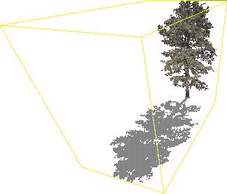
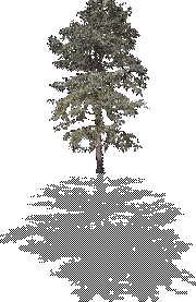
But, for now, there are some workarounds: one is to intersect planes to give an illusion of depth. Another is to actually model the tree using spheres, cones, or more complex modelling and then apply (a) tree texture(s) to it. But however you make a tree, adding a shadow will make it that much more realistic. Note that RW3 has no support for axis-aligned polygons, but AW3 does--but only for around the y-axis (and no option to use the old full axis-aligned method, which will hopefully be added soon because it's easier to see object triangles before they download or happen to get lost among other objects if the wrong name is entered and the world doesn't use a registry; and also for certain effects like glimmers, small plants--bushes, flowers, etc--and was a quick way to make spherical textures--sun, moon, balls--disco, etc--without having to make complex modelled objects). This tree shadow example will be for the nonmodelled, axis-aligned/"sprite"/"facer" style. The shadow is a single horizontal polygon "plane" extending out from the base of the tree to the same length as the tree's height (and can vary depending on how much realism you want the shadow to be in reference to the angle of the light source). To keep it simple, I just use the same height of the object as the length of the shadow. If using the shadow with an axisalignment zorienty tree, do not align the shadow's axis as that will defeat the purpose of a shadow plane. Below is an example of a shadowed version of AlphaWorld's tree3m.rwx: |
modelbegin
# Since both prototypes will use the same materials and textures, it is only necessary to state this information above the first prototype. And since "lit" is the default "texturemode", just use the command "addtexturemode foreshorten", so distortion does not occur, and "filter" so the texture is blurred:
addtexturemode foreshorten filter
# Clamp the texture so it doesn't "seam":
# Set the texture and mask:
texture tree3 mask tree3m
# Define the tree with a prototype (which isn't necessary since these prototypes are only used once, but I find prototyping makes some objects easier to understand and create):
protobegin tree # Place the verts:
vertex -.2 0 0 uv 0 1 # Make polygons:
quad 1 2 3 4 # End the prototype:
protoend
# Here is the shadow prototype:
protobegin shadow
# Use the same verts from the "tree" prototype above:
vertex -.2 0 0 uv 0 1 # Half-opacity is used for the shadow effect, since shadows can be seen through:
opacity .5
# Only quad the back side (which will be made the shadow top later):
quad 4 3 2 1
# End the shadow prototype:
protoend
# Begin the tree clump:
clumpbegin
# Make the tree polygon a sprite:
axisalignment zorienty
# Call the tree prototype from above:
protoinstance tree # Rotate the shadow polygon 90° around the x-axis from the base of the tree plane down towards the camera along the z-axis (yes, visualizing all of these transformations can be annoying):
rotate 1 0 0 90
# If you want an angled shadow (like if the tree will cast its shadow on a 45° hill), use "rotate 1 0 0 45" or whatever degree inclination the hill is at. While it would take a lot of work to get the shadow to follow every polygon angle (depending on the hill's complexity), it's easier to just keep the shadow a flat plane. However, it's relatively easy enough to make a shadow half horizontal and half vertical, for example. But I digress...
# Put the shadow in a nested clump to make it non-solid for AW 2.2 and below:
clumpbegin
# And don't forget the "collision" command for AW3:
#! collision off
# Raise the shadow with a translate statement so it is not flush with any horizontal planes the tree may be on, causing overlapping/"bleeding"/fragmentation from z-buffering. This also saves from having to manually raise the tree one [Shift] movement as a workaround for the "bleeding":
translate 0 0 -.003
# Note: instead of using the above translate, the shadow polygon's vertex depths could have instead all been set to -.003.
# Call the shadow prototype from above:
protoinstance shadow
# End the nested clump:
clumpend
# End the main clump:
clumpend
# End the model:
modelend
|
To create shadows for other objects, it will be easiest to make them for objects that are in-line with the direction of the light source. Then, for simplicity's sake, as in the tree shadow example, make a flat, horizontal plane the length of the object's x or z coordinate (depending on its position relative to the position of the light source) and then use the height of the object as the depth of the shadow. You'll have to experiment with this depending on the object and ground because it will vary considerably.
Once you have the shadow or shadowed object (object with shadow as a part of it), position it correctly so as to enhance the illusion of the light source in a world. AW worlds only have one light source at "approximately mid-afternoon slant" (perhaps around 67.6 degrees) by default. The light source comes from the northwest, so position the shadow pointing southeast. (In AW3 the light by default--it can be changed, however--comes from 8X 5Y 1Z which is 80m west, 50m up, and 10m north--so, basically, still from the same place.) AW 3.1 now allows multiple light sources so be weary of them when creating shadows.
Note: In
Other Objects
![]() Mars world, because the infinite ground object has vertex light sampling, it looks like the light is coming from the southwest, but looking on other objects, the light source seems to be coming from the northwest. Also note that the light source is not coming from directly overhead, as implied by the shadows around Mars' ground zero and in
Mars world, because the infinite ground object has vertex light sampling, it looks like the light is coming from the southwest, but looking on other objects, the light source seems to be coming from the northwest. Also note that the light source is not coming from directly overhead, as implied by the shadows around Mars' ground zero and in ![]() AWGate. Note: light source positions may vary with AW3+.
AWGate. Note: light source positions may vary with AW3+.
Example Worlds
For more examples of shadows in worlds, see:
![]() Mars: and my sites in it
Mars: and my sites in it
![]() ³: \
³: \
![]() Hole: / which have by far the most intricate shadows I've ever seen in any AW world :)
Hole: / which have by far the most intricate shadows I've ever seen in any AW world :)
![]() NRM: uses textured shadows and is the world with the second most intricate shadows in AW that I know of
NRM: uses textured shadows and is the world with the second most intricate shadows in AW that I know of
![]() Rick's: Casablanca theme with above-light shadows for most objects (tables, chairs, etc) inside
Rick's: Casablanca theme with above-light shadows for most objects (tables, chairs, etc) inside
![]() Rubble: trees
Rubble: trees
^ Top